 A micro switch, also known as miniature snap action switch, is a type of momentary contact switch used widely in automotive,industrial and medical instruments as sensor. The switch is termed as “micro” on the name of the company who first started manufacturing it commercially.
The actuator of these switches often has a hinged wheel placed above a push button. This switch is widely used in control system applications such as a door interlock, safety switches in elevators, vending machines etc. Having a diverse range of engineering applications, micro switches are available in various switch configurations, housing materials, actuator styles etc.
But what makes these switches to be called as “snap action” switches? How the momentary contact is managed by the switch? Is there a combination of spring or thin plastic fibers that allow such motion? Continue reading to reveal all the answers.
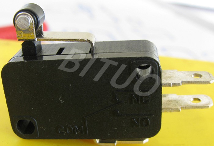
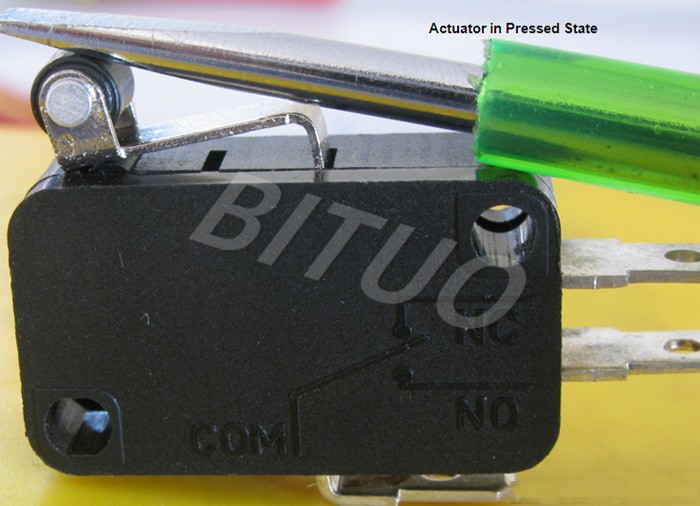
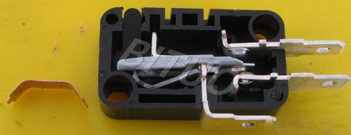
A conventional SPDT micro switch is shown in the image above. It is a blunt edged rectangular structure having three output contact strips denoting common (ground), open and closed state respectively.
Two diagonally opposite holes are dug in to provide easy mounting of the switch on surface. Similarly, holes at the terminals of output contact strips allow easy soldering with the wires. The plastic box can be made of polyester or phenolic plastic products.
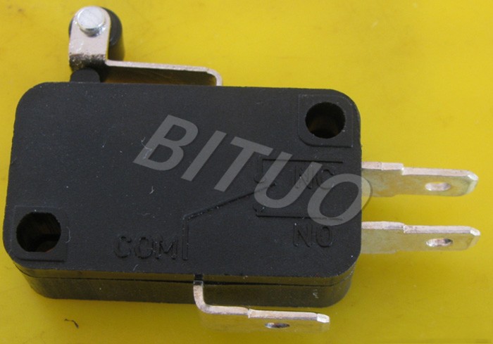
Actuator Assembly
Actuator assembly of the switch is a combination of a hinged wheel and a push button. The images above show the actuator assembly and its movement when switching state is changed.
Movement of Actuator: For this switch as the rest state of this switch is the normally connected position (NC) while the active state, i.e. the state when the actuator is pressed, is the normally open (NO) state of the switch.
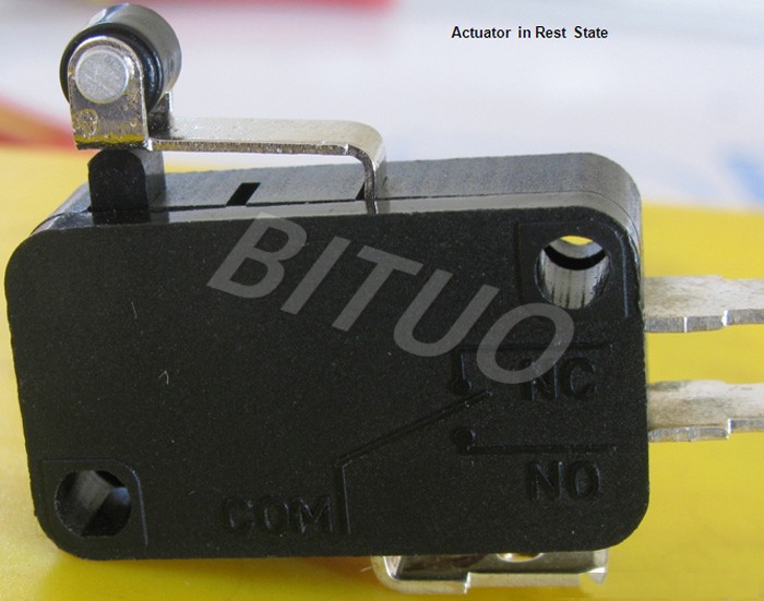
ON and OFF State
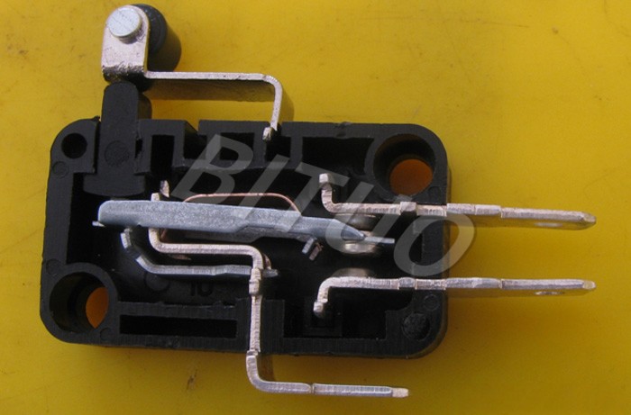
The image above shows the NC or Normally Connected state of the switch. Here, the actuator is not pressed and hence, all other parts stay in their default rest state.
Let’s find out the internal assembly of the switch that responds to the actuator force and changes the state of the switch.
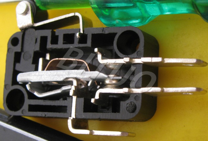
The active state of the switch, i.e., when the actuator is pressed can be seen above. In this image, the movement of the different parts is shown when the actuator is pressed.
Internal Structure
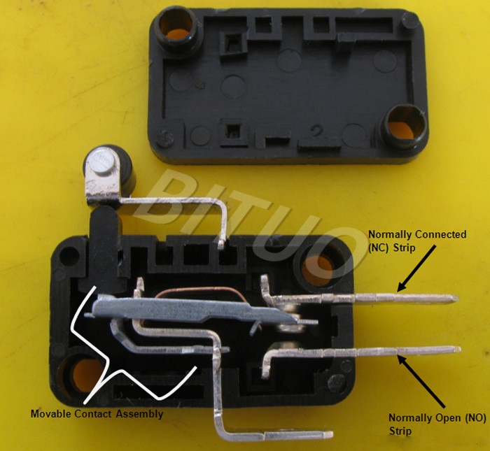
Internal Structure Assembly: On opening the plastic casing of the switch, the different parts of the internal structure of the switch can be seen. It is a simple assembly, comprising of:
- Two stationary contacts for NC and NO position.
- One movable contact assembly.
Movable Contact Assembly
Tensile Metal Strip: The part taken out from the movable contact assembly is a metallic strip shaped like an inverted “U” that is stretched from its sides. This small tensile strip gives the restraining force to the movable contact, bringing it back to its rest state after force from actuator is removed. Working like a spring, this strip is responsible for the “snap” action of the micro switch.
The image above shows the actuator in the pressed state even there is no force upon it. This is due to no resilient force acting on the movable contact to bring it up and push the actuator to its rest state.
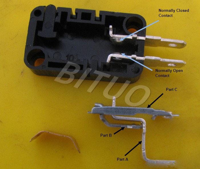
Parts clung to Ground Contact Strip: The rest of the mechanical assembly of the movable contact has been taken out from the plastic base in the image above. The parts are:
- Contact strip serving as common (ground). (Labeled as part A)
- A bent strip placed beneath the actuator assembly. (Labeled as part B)
- A dive board shaped movable contact. (Labeled as part C)
Common Contact Strip
Common Contact Strip: The image above shows stair shaped ground contact strip which also holds the rest of the parts of the movable contact assembly. The upper part of the contact is fixed between the moldings on the plastic base while lower part emerges out as a contact strip.
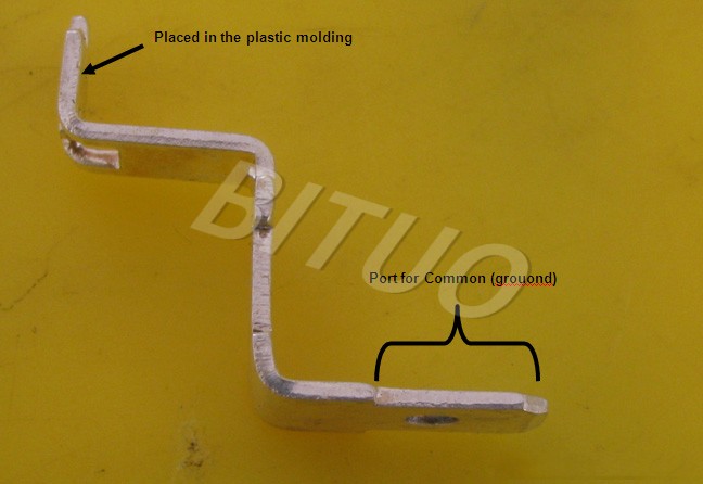
A number of sections have been cut on the plate to allow other parts of the movable contact to cling on.
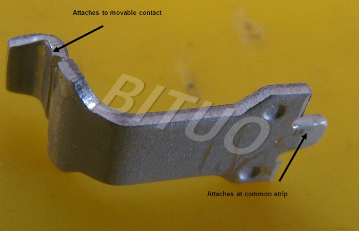
Bent Strip placed beneath actuator
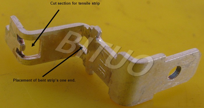
Bent Strip: The bent strip placed beneath the actuator assembly has been shown in the image above. One end of this strip is placed inside a cut section of the ground contact strip and the other end of this strip is placed in a cut section of the movable contact.
The task of this strip is to transfer the force exerted by the actuator to the movable contact which then moves and make connections with the NO contact of the switch.
As soon as the force from actuator is released, the movable contact comes at rest state due to resilient force of the tensile strip and this strip forces the actuator back to its rest state.
Movable Contact
Movable Contacts: The images above show the movable contact from both of its sides and the bulge on each. It has to establish connections with both the output contacts and facilitating it are the bulges on both sides.