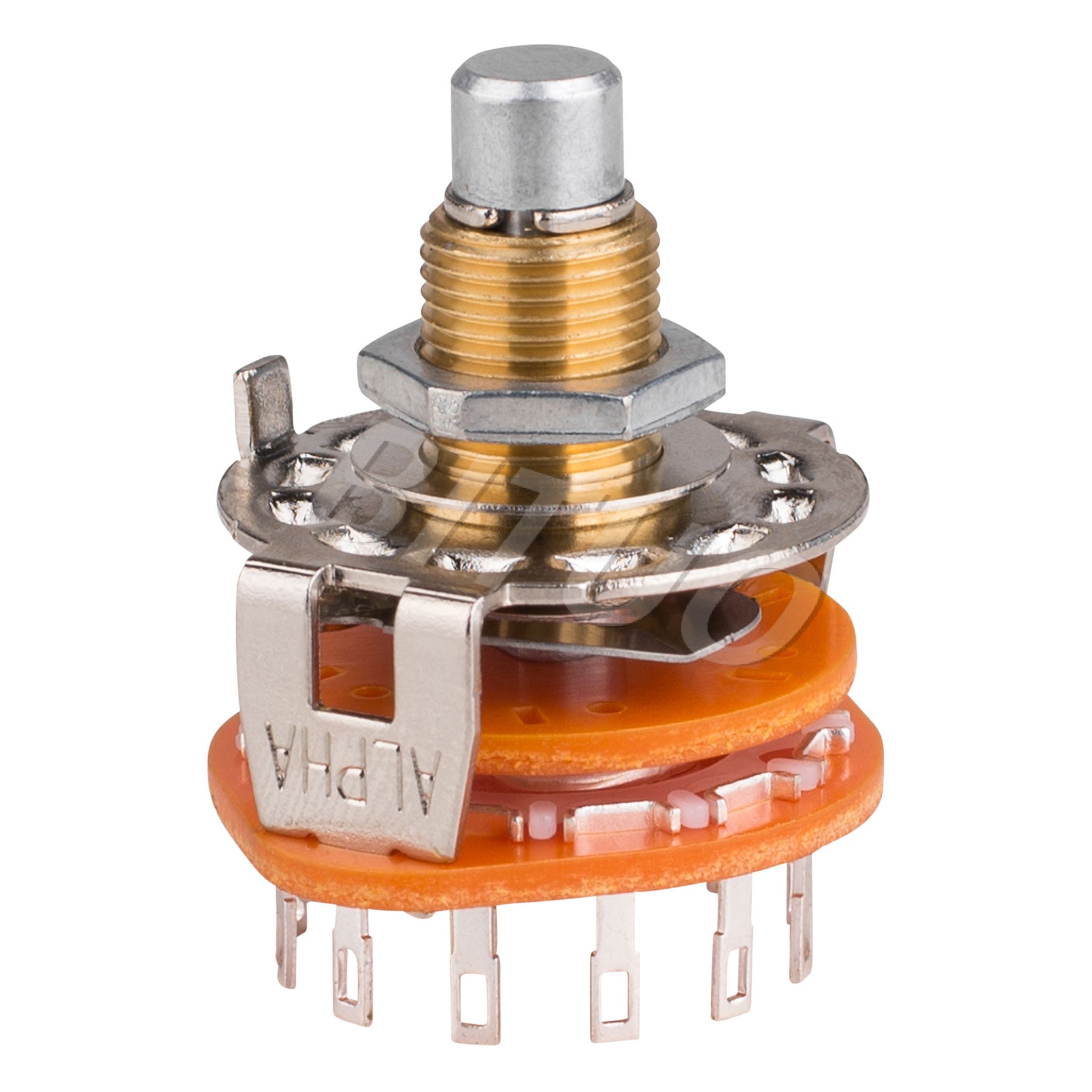
A rotary switch connects several devices to an electric source. The electricity enters the rotary switch’s input terminal and the switch sends electricity to the output terminal selected. Some rotary switches contain more than one circuit. These contain two or more input terminals, called “poles,” and each input circuit connects to multiple output terminals, or “ways.” A 2P4W rotary switch contains two poles and each pole connects to four ways. The center terminals on a rotary switch connect to the electric source and the terminals around the outside of the housing connect to the devices.

Step 1
Find the rotary switch’s “1” output terminal for each input terminal. Some rotary switches have labels stamped into the housing next to the terminals. If not, turn the switch to the “1” position. Place one ohm meter probe on the input terminal and touch the output terminals with the ohm meter’s second probe until the meter reads continuity. Consider the terminal with continuity “1.”
Step 2
Prepare the wire ends for the rotary switch. If the wires solder to the rotary switch terminals, remove 1/4 inch of each wire’s insulation with wire strippers. In all other cases, install the proper terminal connector on each wire.
Step 3
Attach the power supply wire to the rotary switch’s input terminal. If the wires solder to the rotary switch, hold the power supply wire against the input terminal and apply solder with a soldering iron and solder. If the rotary switch uses terminal connectors, push the power supply terminal connector on to the input terminal. Repeat this for each rotary switch circuit.
Step 4
Secure the device wires to the rotary switch’s output terminals with either the terminal connectors or solder. Connect the first device to the “1” terminal, then connect the remaining devices in the order of operation with the second device connected to the terminal clockwise of the first terminal, the third clockwise of the second, and so on. Repeat this on each rotary switch circuit.


