Keywords: Rocker Switch, Electrical Switch, AC vs DC Circuit
This article introduces rocker switches, their main types, and basic wiring methods. It explains how to choose the right switch for AC or DC circuits and provides simple guidance for wiring 3-pin and 5-pin illuminated rocker switches, focusing on safety and reliable operation in automotive and industrial applications.
From design and function to technology and mechanism, electrical switches have come a long way. It is widely used as a circuit element that turns on or off an electric current. These switches are available in a variety of sizes, designs, configurations, and current levels designed to meet the different needs of each application.
Wiring a rocker switch correctly is a fundamental skill for electrical safety and system reliability. Whether you are dealing with a standard 3-pin illuminated switch or a complex 5-pin configuration, understanding the precise pinout logic—Supply, Load, and Ground—is critical to prevent short circuits and component failure. This professional guide provides universal wiring schematics for automotive and industrial applications.
Get a quote for custom products from bituoelec
What are rocker switches?
A rocker switch is a push-button device that allows an on/off transition. They usually have two symbols, a circle for the “on” position and a horizontal line or dash for the “off” position. Rocker switches are sometimes called seesaw switches, and they are common in electronics such as monitors, surge protectors, and computer power supplies.
Types of Rocker Switch
Rocker switches are commonly used in electrical circuits and come in many types, each with its own unique function and application.
Here are some common types of rocker switches:
- Single Pole, Single Throw (SPST)
- Single Pole, Double Throw (SPDT)
- Double Pole, Single Throw (DPST)
- Double Pole, Double Throw (DPDT)
Single Pole, Single Throw (SPST)
SPST (Single Pole Single Throw) switches are designed for circuits that require a single connection between input and output. Its design includes an input and an output.
It is a simple type of switch. When it’s off, the circuit is on. When it’s on, the circuit is off. Its basic design and features make it ideal for circuit applications requiring on-off switching.
The desk fan’s power switch is an SPST (Single Pole Single Throw) device. It controls one circuit and has just one “ON” setting that turns the fan on or off.
Single Pole, Double Throw (SPDT)
SPDT (Single Pole Double Throw) is a switch with one input and two outputs. This means it can be connected to two different output circuits and switched between them, as opposed to SPST (Single Pole Single Throw) which only connects to one output circuit.
The circuit is wired in such a way that the relay can be used as an ON-OFF switch or to connect the circuit to multiple paths. It provides a reliable mechanism for the diversification of circuit functions and allows flexibility in its structure and operation.
This particular desk fan features a rocker switch that allows you to toggle between off, low power, and high power modes. This is a great way to control the temperature of your environment.
Double Pole, Single Throw (DPST)
A DPST switch has two ports, each with a contact. In the run state, called the “ON” setting, the port contacts are closed together. Whereas in the OFF setting, they are on and not connected.
This type of circuit is unique in its ability to accept two inputs and drive two different outputs over the same line. With this feature, the circuit offers a greater range of possibilities than previous models.
DPST circuits have wide applications as they can drive various functions depending on their design. Ultimately, the purpose of these circuits is determined by the circuit design.
The hair dryer has a rocker switch that can be toggled between ON and OFF. When activated, power is sent to two different circuits – one dedicated to the blower motor and one dedicated to the heating element.This special rocker switch with DPST function is able to control two independent circuits with one ON position.
Double Pole, Double Throw (DPDT)
A Double Pole Double Throw (DPDT) switch has six connections and two separate input terminals. The two poles each provide a single connection that can be used to open or close two different circuits.
Double Pole Double Throw (DPDT) switches are the most advanced type of rocker switch available. It’s designed in such a way that each input is connected to two different outputs, and all four outputs are completely independent of each other.
This blow dryer provides increased customization for users through its rocker switch. The switch has two ON positions and functions as an SPDT, offering three different settings: off, low-power, and high-power. With this control over the fan’s power output, users are empowered to personalize their styling experience.
How to Choose a Rocker Switch: AC or DC Circuit?
When selecting a rocker switch for your project, it is crucial to determine whether your circuit operates on alternating current (AC) or direct current (DC). A rocker switch functions as an on/off control, regulating the flow of electricity. However, during operation, it may generate sparks or arcs between its contacts when switching states, and the nature of this transition varies between AC and DC circuits.
AC current alternates direction periodically, causing voltage to fluctuate and naturally reach zero twice per cycle. This characteristic helps extinguish arcs quickly, reducing wear on switch contacts. On the other hand, DC current maintains a constant flow in a single direction, meaning any arc that forms takes longer to dissipate. Prolonged arcing can lead to excessive heat buildup, eventually damaging switch contacts and reducing their lifespan.
Choosing the Right Rocker Switch for Your Application
- High-Voltage and Backup Power Systems:If your system operates at high voltages or has a backup power source, choose a rocker switch rated for 240V AC to ensure long-term durability. These switches are designed to handle the voltage fluctuations inherent in AC circuits, minimizing contact damage.
- Low-Voltage Battery-Powered Systems:For applications running on 12V or 24V DC, such as automotive and marine electrical systems, opt for a DC-rated rocker switch. These switches are built to withstand the continuous flow of direct current without excessive degradation.
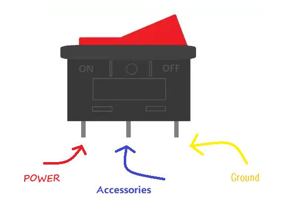
Understanding Rocker Switch Terminals
Proper wiring is essential for the safe and efficient operation of a rocker switch. Here’s a breakdown of the key terminals:
This terminal, typically found on the left side of an illuminated rocker switch, connects to the positive power source (e.g., mains power or battery). It provides a stable input to the switch, ensuring consistent operation.
The central terminal, often labeled as the “Accessories” terminal, distributes power to connected devices or loads. This terminal must be wired to the positive terminal of the load (such as lights or motors) for the system to function correctly.
To enhance electrical safety, the ground terminal should be connected to both the power supply and load ground. Proper grounding prevents electrical faults, reduces the risk of shock, and ensures stable system performance.
Additional Considerations When Selecting a Rocker Switch
- Current Rating:Ensure the switch’s current rating matches or exceeds the maximum current your circuit will draw. Overloading a switch can cause overheating and premature failure.
- Ingress Protection (IP) Rating:For applications exposed to moisture, dust, or extreme conditions, select a switch with an appropriate IP rating to prevent environmental damage.
- Switch Type:Rocker switches come in various configurations, such as SPST (Single Pole Single Throw), SPDT (Single Pole Double Throw), DPST (Double Pole Single Throw), and DPDT (Double Pole Double Throw). Choose the configuration that best suits your circuit
- Illumination:If you need a switch with built-in lighting to indicate its status, ensure it supports the appropriate voltage and wiring setup.
By carefully selecting the right rocker switch and wiring it correctly, you can enhance system efficiency, improve safety, and extend the longevity of your components.
Get a quote for custom products from bituoelec
How to Wire a Rocker Switch: 3-Pin Rocker Switch Wiring?
For optimal results, connect the black wire from a 12-volt power source (i.e., the battery) to the “ground” pin on the rocker switch.
To provide your device extra protection from an overcurrent or electrical surge, it’s important to use a fuse holder to connect the “ACC” wire to one side of the fuse holder. The other side should be connected from the power source (battery) positive connector. Direct connection of wires to the power source should be avoided if possible.
Once you’ve followed the steps above, use an additional wire to plug in from the switch’s “power” connector to the LED light. Once that’s complete, another wire should run between the rocker switch’s “negative or ground” pin and the negative power source (battery) connection to the LED light panel. If you look carefully at the diagram you’ll notice this extra step.
Get a quote for custom products from bituoelec
It is important that you adhere to the soldering guidelines included with your LED light panel, as it will help ensure that all wire connections are properly secured.
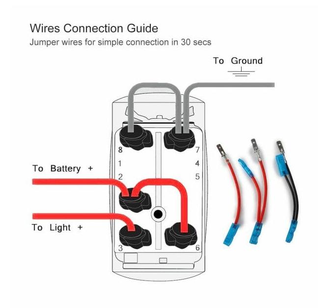
How to Wire a Rocker Switch: 5 Pin Rocker Switch Wiring?
The 5-pin rocker switch has two top pins designated for the ground. The remaining three pins are connected to the power leads; one of them is linked to the dash light circuit and triggers the lower LED on the switch. The last pin is terminated and should be connected to the relay unit (power out).
Step 1: Have your ground and positive jumper cables ready
Connecting the ground connection to the rocker switch requires connecting two pins on the switch to a ground source. For example the negative terminal of a power supply.
Step 2: Connect the positive/hot wire to the 5-pin rocker switch pins
For bridge installation, connect the jumper wires to the switch pins, and then attach them to the hot or positive terminal of the battery. Once complete, test for power.
Step 3: Connect the accessory or the LED pin to the relay
Using a jumper wire, make a connection between the accessory pin and the relay unit. Once it is properly attached, bridge it over to the accessories in the car’s dashboard for proper operation.
Step 4: Connect the T-tap to the wire that controls the interior lights
In order to make sure your interior lights are functioning properly, you’ll need to locate the wire that controls them and attach a T-tap. A T-tap allows you to add a connection without having to cut the wire in half–simply splice it into place. Make sure the T-tap is connected firmly and securely so that the interior light, speedometer, and heat controller all function correctly.
Step 5: Testing
To turn on the parking light or headlights, use the controls located at the lower part of the switch. You should see your instrument panel illumination as well. Lastly, activate the additional lighting controls found on the dashboard.
Common Troubleshooting
LED Won’t Turn Off: This happens when Supply and Load wires are reversed. Ensure the power source is on Pin 2.
Frequent Fuse Blown: Check if the Ground (Pin 3) is accidentally touching the Supply (Pin 2), creating a dead short.
Conclusion
In high-vibration automotive and industrial environments, the quality of the switch determines the system’s lifespan. Bituoelec rocker switches feature Silver Alloy Contacts for superior conductivity and PA66 Flame-Retardant Housing to withstand thermal stress. Our designs prioritize minimal contact resistance, preventing the arcing and overheating common in low-quality alternatives. Bituoelec offers professional OEM/ODM services for industrial and automotive switch solutions worldwide.
Frequently Asked Questions
A: This is a common wiring error where the Supply (Pin 2) and Load (Pin 1) wires are reversed. When the power is connected directly to the load pin, the LED receives constant current. Simply swap these two wires to fix the issue.
A: While the mechanical switch can handle the current, the internal LED is rated for 12V. Using it in a 24V system will likely burn out the indicator light. Always choose a switch rated for your specific system voltage.
A: A 3-pin switch is a basic ON/OFF control with one light. A 5-pin switch typically has two LEDs (backlight and work light) and allows for more complex circuit controls like DPDT (Double Pole Double Throw).