


You press a button on a TV remote and feel a small click under your thumb. That click is a tact switch. It is one of the most produced electronic components in the world, found inside everything from car key fobs to medical infusion pumps.
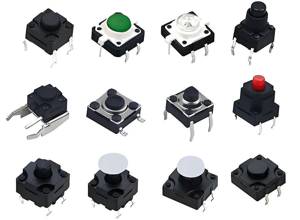
Bituoelec manufactures tact switches in a range of sizes, actuation forces, and mounting styles for consumer electronics, industrial controls, and medical devices. This guide covers how they work, what types exist, and how to pick the right one for your PCB.
What Is a Tact Switch and How Does It Work
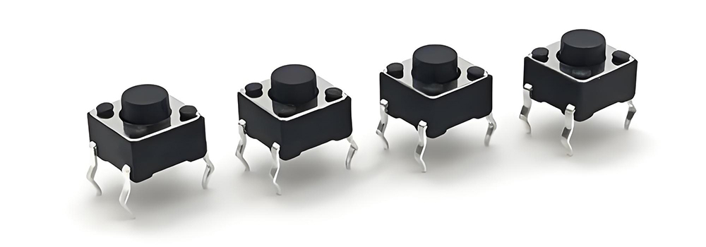
A tact switch, short for tactile switch, is a small momentary push button designed for direct mounting on a printed circuit board. It is normally open. Press the actuator and the internal contacts close. Release it and the contacts spring back open. The defining feature is tactile feedback.
A small metal dome inside the switch snaps when pressed, producing a physical sensation and often an audible click. The user knows the switch engaged without needing a visual indicator.
Tact switches are designed for low current, low voltage applications. Typical ratings are 50mA at 12VDC. They are not meant to switch household AC loads or high-power circuits. They are signal-level components.
Inside a Tact Switch: The Metal Dome and Click Mechanism
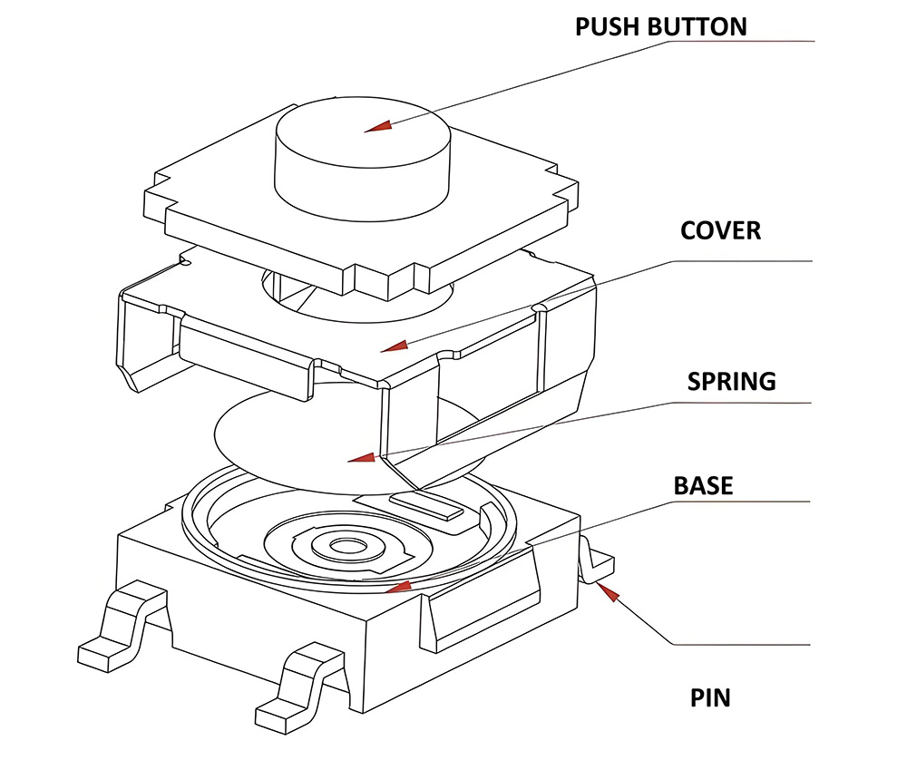
The core of every tact switch is a thin metal dome, usually made of stainless steel or phosphor bronze. The dome sits over two fixed contacts on the base of the switch. When you press the actuator from above, the dome deforms and snaps downward, bridging the two contacts and completing the circuit.
When you release, the dome snaps back to its original curved shape and the circuit opens. This snap action gives the switch two properties. First, the sharp click provides tactile feedback.
Second, the fast make-and-break action minimizes contact bounce and arcing, which improves reliability at low signal levels. The dome also serves as the return spring. There is no separate coil spring in a basic tact switch. The dome does both jobs.
Tact Switch vs. Push Button Switch: What Is the Difference
A push button switch is a broader category. Push buttons can handle higher currents, come in larger panel-mount form factors, and often have separate spring and contact mechanisms.
A tact switch is a specific type of push button optimized for PCB mounting and low-power signal switching. It is smaller, cheaper, and designed for high-volume automated assembly.
The key practical difference: push button switches are typically mounted on the outside of a device enclosure. Tact switches are mounted inside, on the PCB, with a plastic button cap or overlay membrane sitting between the user’s finger and the switch actuator.
Types of Tact Switches by Mounting Style
Through-Hole (THT)
Through-hole tact switches have pins that go through drilled holes in the PCB and are soldered on the opposite side. They are mechanically strong and easy to hand-solder for prototyping.
Common pin layouts are two-pin and four-pin. Four-pin versions have two pairs of connected pins for stability. The standard footprint is a 6mm x 6mm square, with pin spacing of 4.5mm or 5mm.
Surface Mount (SMD)
Surface-mount tact switches sit on top of the PCB with solder pads rather than through holes. They are smaller, lighter, and compatible with automated pick-and-place assembly lines.
Common sizes are 3mm x 2mm, 4.5mm x 4.5mm, and 6mm x 6mm. SMD tact switches save board space and cost in high-volume production. The tradeoff is mechanical strength. An SMD switch can lift off the board under heavy sideways force if not supported by the enclosure design.
Sealed and Side-Actuated
Sealed tact switches have a rubber membrane or silicone boot that protects the internal dome from dust and moisture during PCB washing and in service.
They are rated to IP67 in some designs. Side-actuated tact switches have the actuator on the edge of the package rather than the top. They suit designs where the button is pressed from the side of the PCB, such as edge-mounted controls on handheld devices.
Illuminated Tact Switches: LED Options and Design Tips
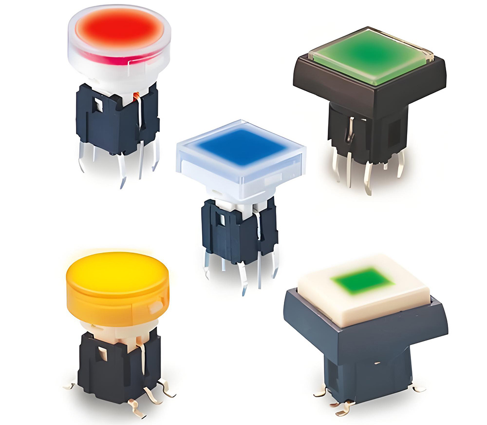
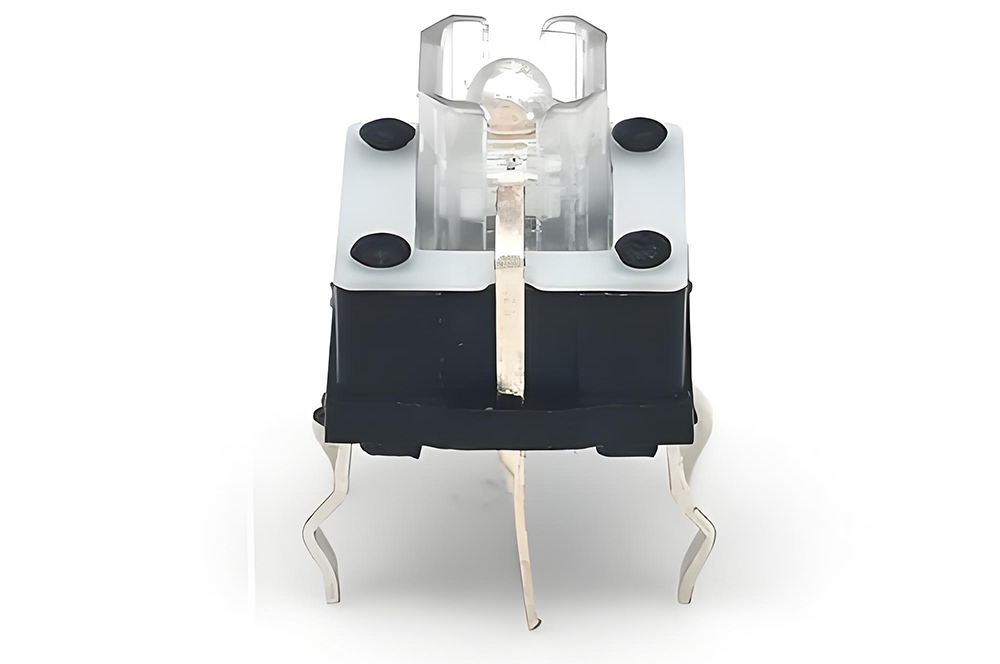
An illuminated tact switch has a built-in LED, usually a single-color SMD LED mounted on the switch body or the PCB underneath a translucent actuator. Common LED colors are red, green, blue, white, and amber. The LED can be wired independently of the switch contacts, which gives the designer full control over when and how it lights.
You can have the LED stay on all the time as a backlight or pulse it when the button is pressed. LED forward voltage is typically 2V to 3.3V. If the circuit runs at 5V or 12V, add a current-limiting resistor.
The resistor value depends on the LED current rating, typically 10mA to 20mA. For a 5V circuit with a 2V LED at 15mA, use a 200-ohm resistor. Illuminated tact switches come in SMD, through-hole, and panel-mount versions.
Key Specifications: Operating Force, Travel, and Life
Operating Force and Travel
Operating force is how hard you need to press to close the switch. Common values are 100gf, 160gf, 260gf, and 350gf. A TV remote button might use 160gf for a satisfying click without requiring much effort. An industrial control panel might use 350gf to prevent accidental presses.
Total travel is the distance the actuator moves from rest to the contact point. It is typically 0.2mm to 0.5mm. Overtravel is extra travel beyond the contact point before the actuator bottoms out. It provides a safety margin for assembly tolerances.
Mechanical and Electrical Life
Mechanical life for a standard tact switch ranges from 100,000 to 1 million cycles. Electrical life at rated load is shorter, typically 50,000 to 200,000 cycles. For designs that expect heavy use, such as gaming controllers or industrial keypads, choose a switch with a rated life of at least 500,000 cycles.
Check the bounce time as well. Contact bounce is the brief period where the contacts chatter before settling. It typically lasts 5ms to 10ms. Microcontroller firmware should include a debounce routine that ignores input for 10ms to 20ms after the first edge detection.
Common Applications Across Consumer and Industrial Electronics
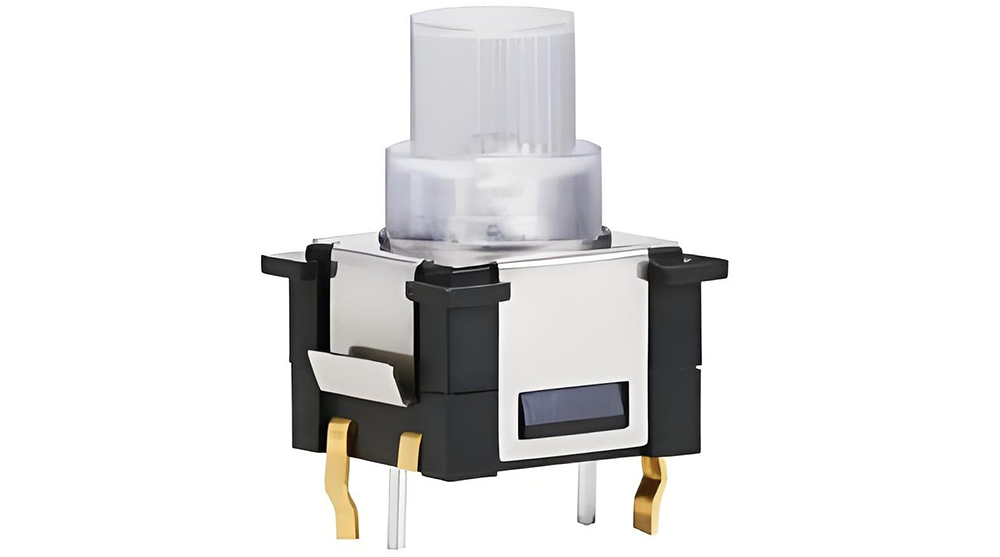
Consumer electronics are the largest market. TV remotes, game controllers, microwave keypads, calculator buttons, and computer keyboard switches all use tact switches.
Automotive interiors use them for steering wheel controls, dashboard buttons, and seat memory switches. Medical devices use sealed tact switches on infusion pumps, patient monitors, and diagnostic equipment where liquid ingress is a risk. Industrial equipment uses tact switches on handheld programmers, CNC control pendants, and test and measurement gear.
Vending machines and POS terminals use tact switches behind membrane overlays for product selection keypads. In all these applications, the tact switch provides the physical click. A plastic cap or rubber overlay transfers the user’s press to the switch actuator underneath.
How to Select the Right Tact Switch for Your PCB Design
Start with the mounting style. Through-hole for prototyping or low-volume production where hand soldering is practical. SMD for automated high-volume assembly.
Sealed if the board goes through a wash process or operates in a humid environment. Side-actuated if access is from the edge of the enclosure. Then pick the operating force. 160gf for consumer devices, 260gf for industrial equipment.
Check the actuator height. Tact switch actuator heights range from 0.5mm to 10mm or more. The actuator height plus the button cap thickness must match the distance from the PCB surface to the inside of the enclosure.
Common standard heights are 4.3mm, 5mm, 7mm, and 9.5mm. Verify the PCB footprint against the switch data sheet before ordering. The 6mm x 6mm package is the most widely available, but pin spacing and pad size can vary between manufacturers.
Browse Bituoelec tact switch product line for through-hole, SMD, sealed, and illuminated options.
Installation and Soldering Guidelines
Hand Soldering Through-Hole Tact Switches
Insert the pins through the PCB holes and bend the leads slightly outward on the underside to hold the switch in place before soldering. Use a temperature-controlled iron at 350 degrees Celsius.
Apply heat to the pad and the pin simultaneously for one to two seconds, then feed solder into the joint. Do not apply heat for more than three seconds. Excessive heat can soften the plastic body and warp the internal dome. Let the joint cool naturally. Do not blow on it.
Reflow Soldering SMD Tact Switches
SMD tact switches are designed to survive reflow soldering temperatures, typically peaking at 250 to 260 degrees Celsius. Check the switch data sheet for the reflow profile. Sealed switches with a rubber membrane have a lower peak temperature tolerance.
If the switch has a removable actuator cap, remove it before reflow. The cap may not survive the oven temperature without warping. Some manufacturers ship the caps separately for this reason. After soldering, press each switch to confirm the click. A switch that feels mushy or does not click may have absorbed flux or solder paste into the mechanism. Replace it.
Bituoelec Tact Switch Solutions
Bituoelec manufactures tact switches in through-hole and surface-mount packages with a range of actuator heights, operating forces from 100gf to 350gf, and sealed and illuminated options.
Standard 6mm x 6mm footprints are available for quick integration into existing designs. Custom actuator colors, actuator caps, and pre-assembled keypad arrays are available through OEM and ODM services.
Frequently Asked Questions
Q What is the difference between a tact switch and a micro switch?
Both use a snap-action mechanism. A micro switch switches higher currents and has a longer mechanical life, often 1 million to 10 million cycles. A tact switch is smaller, PCB-mounted, and designed for low-current signal switching, typically 50mA at 12VDC. Use a micro switch for limit sensing and power switching. Use a tact switch for user interface buttons on a PCB.
Q How do I know what operating force to choose?
For consumer devices pressed by a finger, 160gf gives a satisfying click without tiring the user. For industrial equipment where accidental presses should be avoided, 260gf or higher. For devices operated by children or people with limited hand strength, 100gf.
Q Can I use a tact switch for a power button?
Only if the circuit uses low-voltage DC and the current is under 50mA. A tact switch cannot safely switch 120VAC household current. For mains voltage, use a push button or rocker switch rated for the load.
Q What is contact bounce and how do I handle it?
Contact bounce is the brief chatter of the contacts in the first 5ms to 10ms after pressing or releasing. It can cause a microcontroller to register multiple presses from a single physical press. Add a software debounce routine that waits 10ms to 20ms after the first edge detection before reading the final state.
Q Do I need a sealed tact switch?
If the PCB goes through a wash process after soldering, yes. Flux residue and water can contaminate an unsealed switch dome. If the device operates in a humid, dusty, or splash-prone environment, a sealed switch prevents long-term corrosion of the internal contacts.
Q Where can I order tact switches in bulk?
Bituoelec supplies tact switches in standard 6mm x 6mm and custom footprints with a range of actuator heights, operating forces, and sealing options. Contact us for volume pricing and OEM customization.