


PCB Design Reference
A single button press does not always produce a single clean electrical signal. When mechanical contacts open or close, they can briefly make and break contact several times, causing the circuit to register multiple inputs. This behavior is known as contact bounce, and managing it is an important part of reliable PCB design.
This guide explains why switch bounce occurs and how hardware and software debouncing methods can help prevent false or repeated inputs.
What Is Switch Bounce?
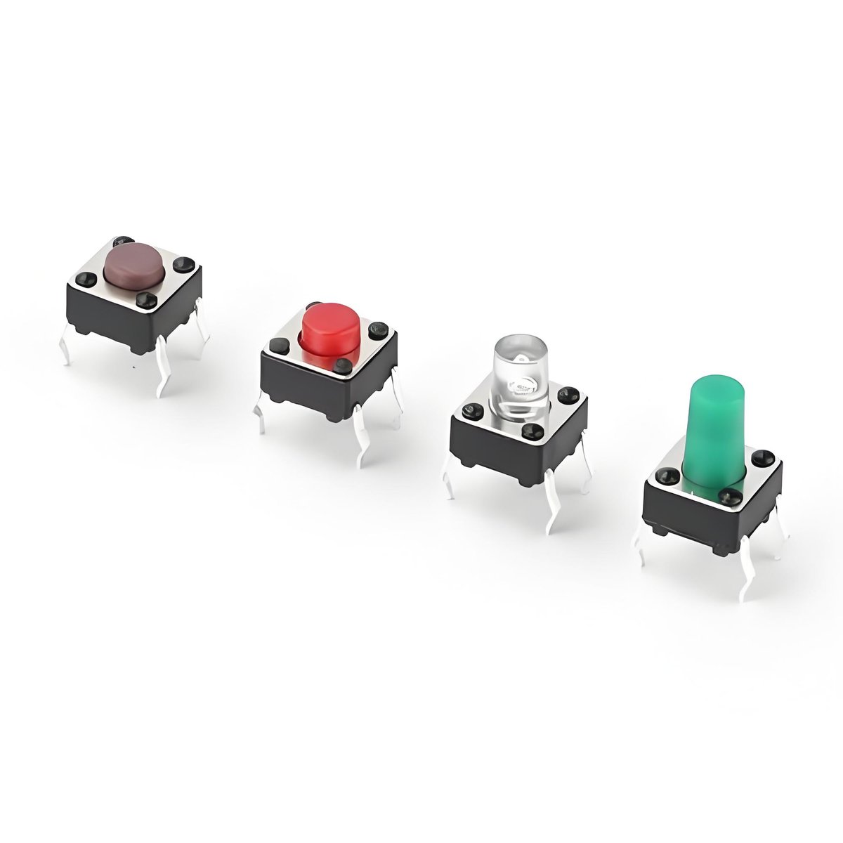
When two metal contacts close, they do not meet in one clean instant. The moving contact rebounds like a small spring, breaking and remaking the connection several times over a short window before it settles. Those rapid make and break cycles are contact bounce, and every mechanical switch shows it to some degree.
The bounce window is short, usually a fraction of a millisecond up to a few milliseconds, but a microcontroller samples its input pins thousands of times per second. From the chip’s point of view, one press looks like a rapid burst of presses. The exact duration varies by switch model and even between individual samples, so check the datasheet of the specific part for typical values.
Bounce is not a defect in the switch. It is a physical property of metal contacts and moving actuators, and it has existed as long as switches have. The job of the designer is to account for it, and the tool for that job is debouncing.
How Switch Bounce Causes False Triggers
A microcontroller detects changes in the signal at its input pin. When a mechanical switch bounces between HIGH and LOW several times within a few milliseconds, the controller may interpret a single press as multiple inputs if no debouncing method is used. This can cause counters to skip values, menus to move more than one step, or commands to execute repeatedly.
The effect varies by application. In a guitar pedal, one press may cause the effect to toggle more than once. An automotive switch may send duplicate commands, while a tact switch on an industrial control panel may register multiple inputs from a single press.
Contact bounce is a normal characteristic of mechanical switches rather than necessarily a sign of switch failure. Reliable designs account for this behavior by filtering or processing the signal before it is treated as a valid input. Depending on the application, this can be achieved through hardware, software, or a combination of both.

Hardware Debouncing with RC Filters and Schmitt Triggers
An RC low-pass filter is a common hardware method for switch debouncing. The resistor and capacitor create a time constant that filters out rapid voltage changes caused by contact bounce, allowing the circuit to produce a more stable transition at the input.
RC time constant
τ = R × C
Component values should be selected according to the switch bounce duration and the requirements of the input circuit. The RC time constant (τ = R × C) needs to provide sufficient filtering without introducing unnecessary response delay. Since bounce characteristics vary between switch models, refer to the switch datasheet when determining suitable values.
Because an RC network produces a relatively slow voltage transition, the signal may spend some time near the logic threshold. A Schmitt trigger can be added after the RC filter to convert this transition into a clean digital signal. Its hysteresis provides separate rising and falling thresholds, helping prevent repeated switching when the input is close to the threshold.
Combining an RC filter with a Schmitt trigger provides a simple and reliable hardware debouncing solution, particularly for designs where a stable digital input is required without relying entirely on software.
Software Debouncing: Delay and State-Validation Methods
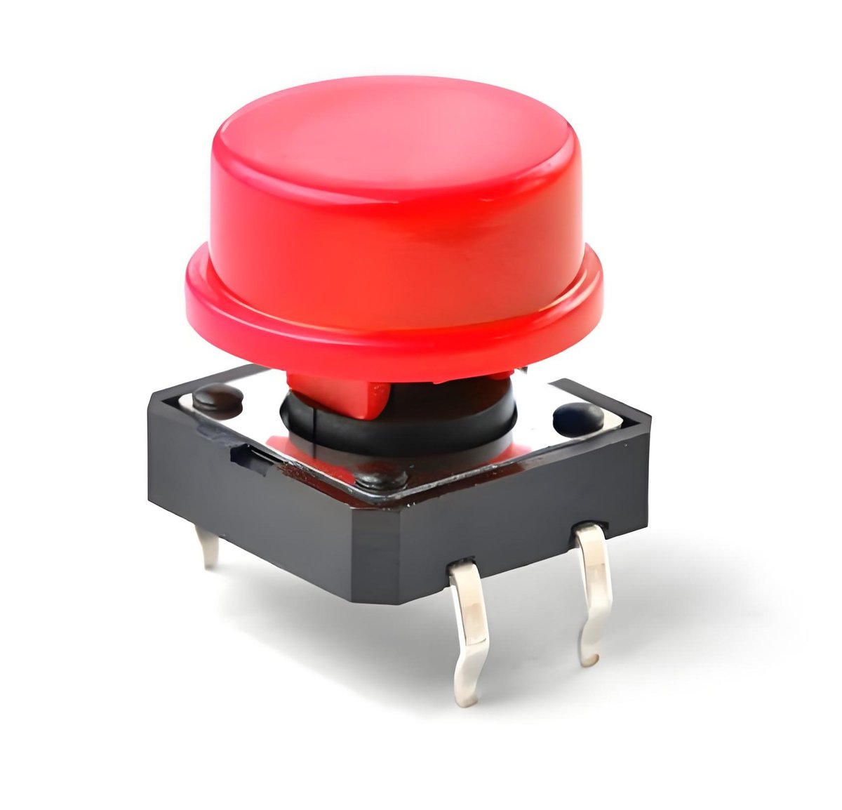
Software debouncing filters switch bounce in firmware without adding components to the PCB. Two common methods are delay-based debouncing and state validation.
Delay-based debouncing
With delay-based debouncing, the firmware detects a state change and waits for a defined interval before accepting another input. This approach is straightforward, but the delay should be implemented carefully to avoid blocking other time-sensitive tasks.
State validation
State validation samples the switch input at regular intervals and accepts a change only after the new state remains stable for a specified period or number of samples. This non-blocking approach is often better suited to systems that need to handle multiple tasks or inputs.
The debounce interval depends on the switch and application. Values in the range of several to tens of milliseconds are commonly used as a starting point, but the switch datasheet and actual measurements should guide the final setting. The interval should be long enough to reject contact bounce without introducing noticeable input latency.
Hardware vs. Software Debounce: A Comparison
| Approach | Strengths | Limitations | Best For |
|---|---|---|---|
| Hardware (RC filter plus Schmitt trigger) | No firmware dependency, deterministic timing, works with any switch | Adds components and board space, values must match the switch’s bounce | High-reliability designs, products without a microcontroller, noisy environments |
| Software (delay or state confirmation) | No extra components, easy to tune after production, costs nothing to change | Needs microcontroller time, changes require a firmware update, poor tuning can miss fast presses | Microcontroller-based products, prototypes, cost-sensitive designs |
When Bounce Matters: Tact Switches and Encoders
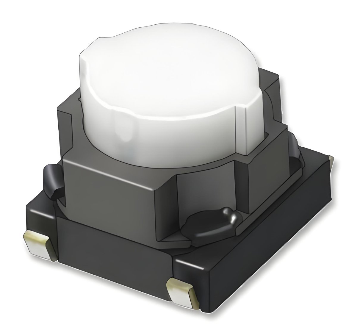
Tact switches are where bounce shows up most often. They are small, inexpensive, and everywhere: front panels, handheld devices, guitar pedals, and appliance controls. Their short travel and light actuation invite fast presses, and fast presses are exactly when bounce is most visible.
Rotary encoders deserve special attention. An encoder produces a sequence of pulses on two channels, and the firmware decodes direction from the order of those pulses. Bounce on either channel can corrupt the sequence, causing the encoder to count the wrong direction or skip steps. Debouncing the encoder channels, or decoding with a state machine that rejects invalid transitions, is a practical requirement for most knob-based interfaces.
Anti-vandal and industrial switches bounce too, though their larger contacts often settle more predictably. The rule does not change: any mechanical contact that feeds a digital input deserves debouncing, and the datasheet is your best guide to how much you need.
Testing and Verification: What We Check at BITUO
Consistent mechanical and electrical performance is important for reliable switch operation. At BITUO, production testing includes key parameters such as actuation force, contact resistance, and electrical continuity, with sample inspections used to monitor performance consistency. Contact behavior can change with mechanical wear, so switch performance should be considered over the expected service life.
For PCB validation, an oscilloscope or logic analyzer can be used to measure the actual bounce duration. Test the switch repeatedly under representative operating conditions and compare the measured waveform with the selected hardware or software debounce interval. The debounce setting should provide sufficient margin while maintaining the required response time.
For applications exposed to varying environmental conditions, testing across the specified temperature and humidity range can provide additional confidence in the design.
Conclusion
Choosing the right switch involves more than matching basic electrical ratings. Contact design, actuator structure, mounting method, operating environment, and expected service life can all affect long-term performance, including contact bounce.
At BITUO, we offer more than 6,000 switch and electronic component models across 24 product series, serving applications in automotive electronics, industrial equipment, consumer electronics, audio products, and custom OEM projects. Our team can help you evaluate your application requirements and identify a suitable standard or customized solution.
Share your circuit specifications, mounting requirements, operating conditions, and preferred debounce method with us. We can recommend suitable switch models, provide technical documentation and samples, and support OEM or ODM development when customization is required.
Contact BITUO to discuss your next PCB or switch project.