


Machine Safety Guide
An emergency stop button is a critical part of a machine safety system, designed to help operators stop hazardous motion or processes in an emergency. Selecting the correct switch and wiring it properly requires careful consideration of its contact configuration, reset mechanism, electrical ratings, and applicable safety requirements.
In this guide, we explain how emergency stop buttons work, how they differ from standard push buttons, basic wiring principles, and the key factors to consider when selecting one for your application.
What Is an Emergency Stop Button?
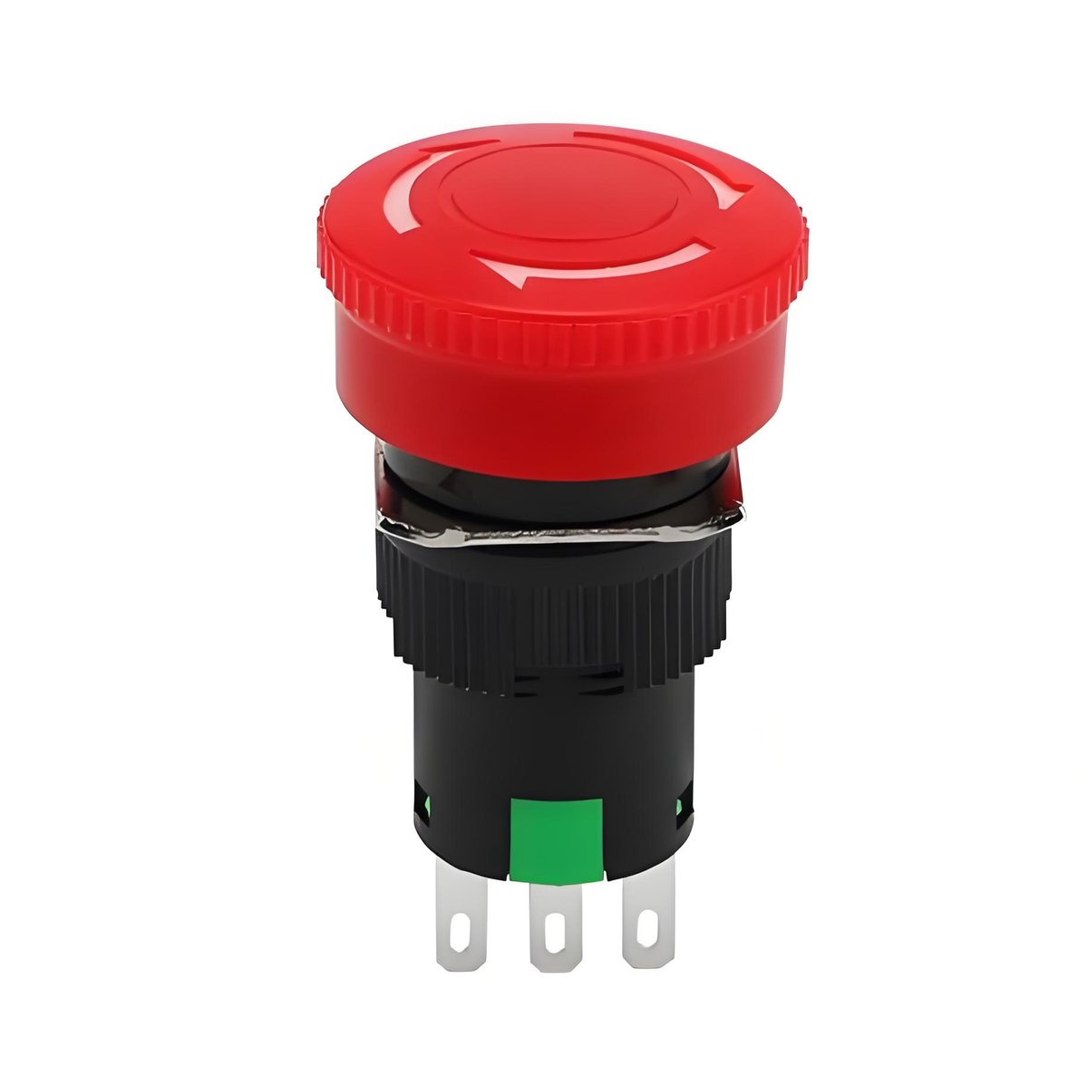
An emergency stop button is a manually operated control device that an operator presses to quickly stop hazardous machine motion during an emergency. You will recognize it immediately: a large red mushroom-shaped actuator set on a yellow background, usually mounted at eye level or within easy reach of the operator station. Pressing it latches the button in the pressed position, so the stop condition stays active until someone deliberately resets it.
An emergency stop button is a control circuit device, not a power switch. It does not carry the full motor current. Instead, pressing it opens the control circuit and causes the machine’s contactor, relay, or drive to drop out, which removes power from the hazardous motion. Small, low current contacts can therefore safely command a large stopping function.
Emergency Stop Button vs. Normal Push Button
At first glance the two look similar, but they are built for completely different jobs. Here is a quick comparison:
| Feature | Emergency stop button | Normal push button |
|---|---|---|
| Purpose | Stop hazardous motion in an emergency | Start, stop, or change a normal machine function |
| Actuator | Large red mushroom head on yellow background | Round, square, or rectangular cap in any color |
| Contact state | Normally closed (NC) in the control circuit | Normally open (NO) or NC, depending on function |
| Action after press | Latches and stays pressed until reset | Momentary or maintained, per the function |
| Reset | Deliberate twist or pull release | No special reset required |
The differences are not cosmetic. A normal push button is meant for frequent, routine operation. An emergency stop button is meant for rare, high stress events, so its mechanics and contact behavior are designed around reliability under pressure. If a panel spec calls for an emergency stop button, do not substitute an ordinary push button in the same cutout.
Safety Standards and Direct Opening Action
Standards focus
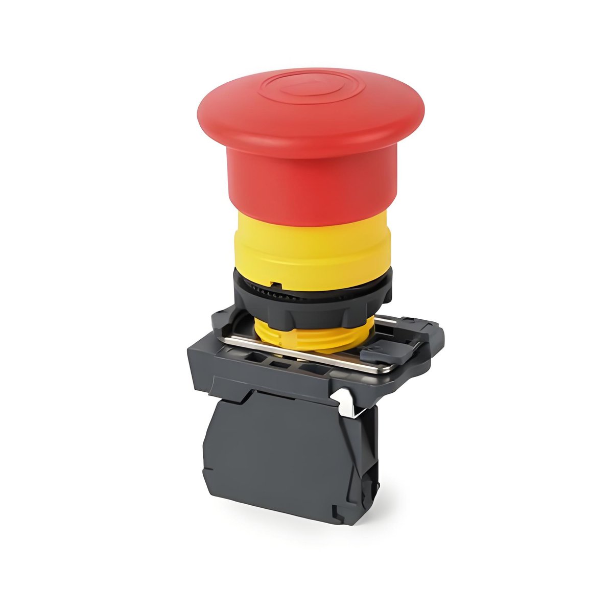
An emergency stop device is more than a standard push button with a red actuator. One important safety feature is direct opening action, as defined in IEC 60947-5-1 for electromechanical control circuit devices.
With direct opening action, operation of the actuator mechanically forces the normally closed (NC) contacts to open. This positive mechanical action helps ensure that the stop circuit is interrupted when the emergency stop is activated, rather than relying solely on spring force.
IEC 60947-5-5 provides additional requirements for electrical emergency stop devices with a mechanical latching function. Emergency stop actuators are typically red with a yellow background, providing clear and consistent identification on machinery and control panels.
When selecting an emergency stop button, verify that the device is designed and tested to the applicable safety standards and that its specifications meet the requirements of the machine and safety circuit.
Emergency Stop Button Wiring: NC Contacts and Series Connection
Emergency stop buttons commonly use normally closed (NC) contacts in the safety circuit. Under normal conditions, the contacts remain closed. Pressing the emergency stop opens the contacts and signals the safety system to bring the machine to a safe stop. This arrangement can also help detect certain wiring faults, such as an open circuit or disconnected wire.
Where multiple emergency stop devices are required, they are typically integrated into the same safety system so that activating any one of them initiates the stop function. The exact circuit architecture depends on the required safety level, machine design, and applicable standards.
When selecting and installing an emergency stop button, check that the contact ratings match the control voltage and current specified for the circuit. Wiring should be properly secured and protected from mechanical stress, and all connections should follow the machine’s electrical schematic.
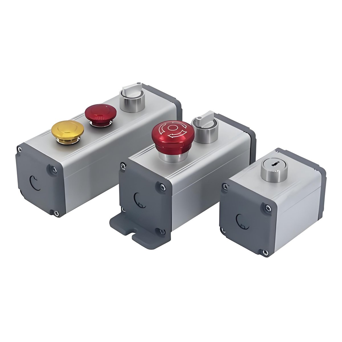
Emergency stop devices are generally connected to a dedicated safety relay, safety controller, or safety-rated PLC input rather than directly switching motor power. The complete safety circuit should be designed and validated according to the machine’s risk assessment and applicable safety standards.
Latching vs. Twist-Release
Latching hold
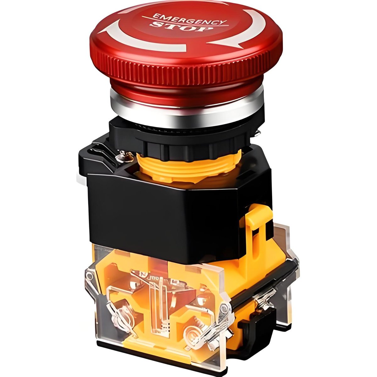
A defining behavior of an emergency stop button is latching: when the operator presses the mushroom head, the mechanism locks and holds the pressed position. The stop condition stays active even if the operator walks away, and the machine cannot restart by itself. This is a deliberate safety feature, not a quirk.
Twist or pull reset
To restart, someone must reset the button by hand. The most common method is twist-to-release: turn the red mushroom head in the indicated direction and the mechanism snaps back to the ready position. Some models use pull-to-release instead. Twist-release dominates industrial panels, while pull-release versions suit applications where twisting is awkward or panel space is tight.
The key point is that reset is a conscious action. The operator has to walk to the button, examine the situation, and deliberately reset it before the machine can start again. That deliberate step is what prevents the classic accident where someone clears a jam, hits start from across the room, and the machine moves while a coworker is still inside it.
How to Select an Emergency Stop Button for Your Machine
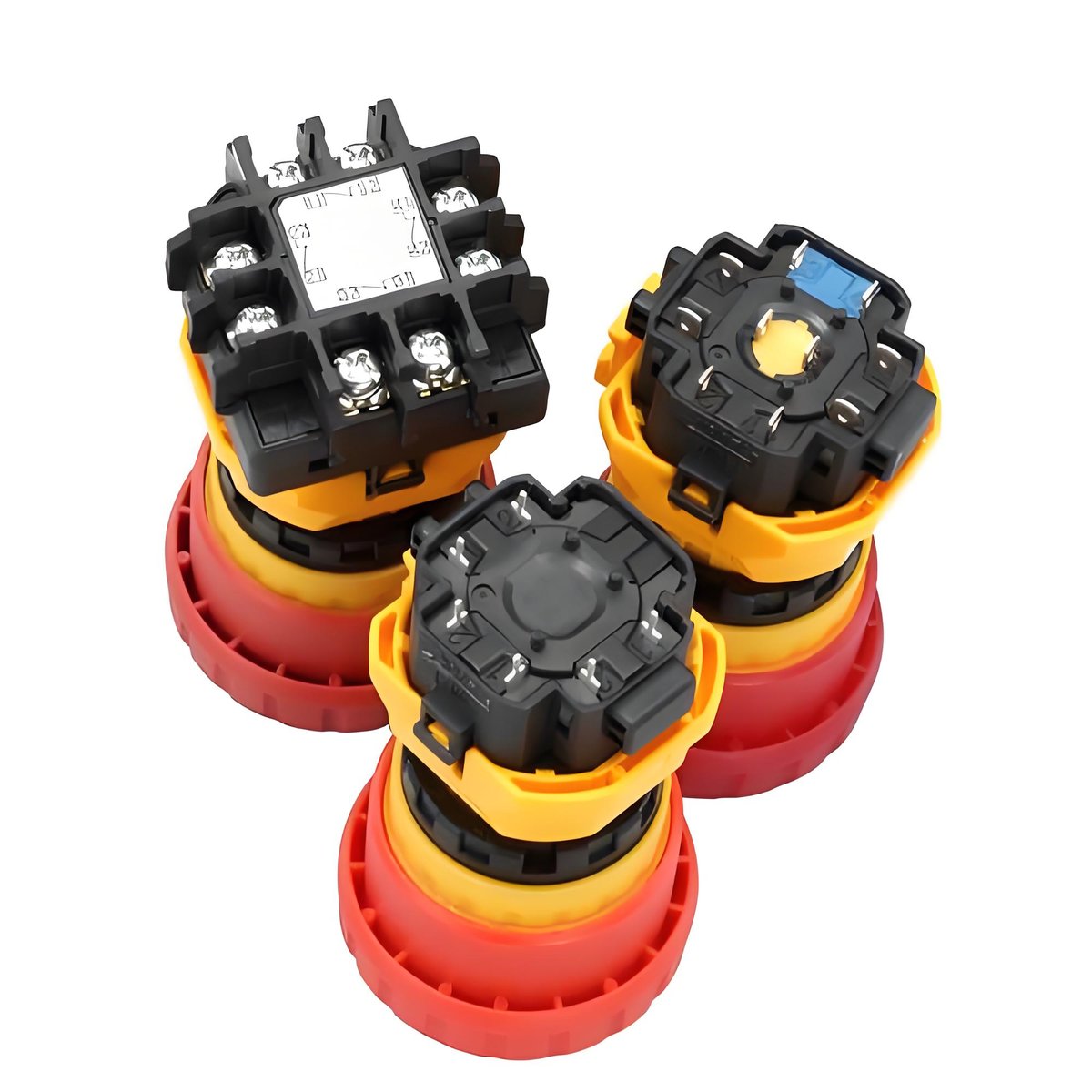
- 01Start with the mounting size. A 22 mm panel cutout is widely used for industrial control devices, while 16 mm, 25 mm, and 30 mm options are also available. Always confirm the panel dimensions before selecting a model.
- 02Next, determine the required contact configuration. Emergency stop devices commonly use normally closed (NC) contacts, with single- or multiple-contact configurations available depending on the safety circuit design. For systems that require redundant channels or monitoring, select a contact arrangement that meets the requirements of the safety system.
- 03Electrical ratings should match the control circuit, including voltage, current, and AC or DC load. Refer to the product datasheet for the ratings of the specific model rather than relying on general specifications.
- 04The operating environment is another important consideration. For equipment exposed to dust, moisture, or washdown, check the required IP rating and make sure the complete installation provides suitable environmental protection.
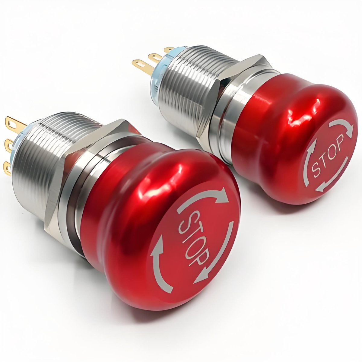
- 05Actuator size and accessibility should also be considered. Mushroom-head emergency stop buttons are designed for quick identification and operation, with different diameters available to suit the panel layout. The number and location of emergency stop devices should be determined by the machine design and risk assessment so they are readily accessible when needed.
- 06Finally, verify that the selected model complies with the standards and approvals required for your application and market. Check the manufacturer’s technical documentation for applicable IEC standards, CE conformity, UL certification or recognition, and other relevant approvals.
Emergency Stop Testing and Maintenance
Emergency stop devices should be inspected and functionally tested at intervals defined by the machine manufacturer, maintenance program, risk assessment, and applicable safety requirements.
During a functional test, activate each emergency stop device and verify that the machine responds as intended. After resetting the device, confirm that resetting alone does not automatically restart the machine. Testing should only be carried out under controlled conditions, with appropriate safety procedures in place.
Visual and mechanical inspection is also important. Check that the actuator moves and latches correctly, markings remain clearly visible, seals are intact, and terminals show no signs of looseness, corrosion, overheating, or damage. Any device that is damaged or does not operate consistently should be investigated and replaced when necessary.
Keep records of inspections, functional tests, and any corrective actions as part of the machine’s preventive maintenance program.
Emergency Stop Button FAQ
Conclusion
Selecting an emergency stop button requires more than choosing the right size. Panel cutout, contact configuration, electrical ratings, environmental protection, and safety requirements should all be considered as part of the machine’s overall safety design.
If you are selecting an emergency stop button for a new machine or replacing an existing device, send us your panel cutout, control voltage, contact requirements, and operating conditions. Our team can help identify suitable models and provide the relevant technical information and samples for evaluation.
Contact BITUO to discuss your emergency stop button requirements or explore our switch solutions for your next project.