


An illuminated anti-vandal switch has an LED built into the bezel, and that LED shares nothing electrically with the switch contacts, so it must be wired as a separate circuit. The contacts switch the load, while the LED is a lamp inside the same housing that needs its own supply path and current limit.
Most failures come from treating four terminals as one circuit. The supply gets landed across the contacts, the lamp lights only while the button is held, or 12 V reaches an LED with no resistor and destroys it.
What the Four Terminals Do
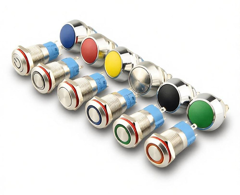
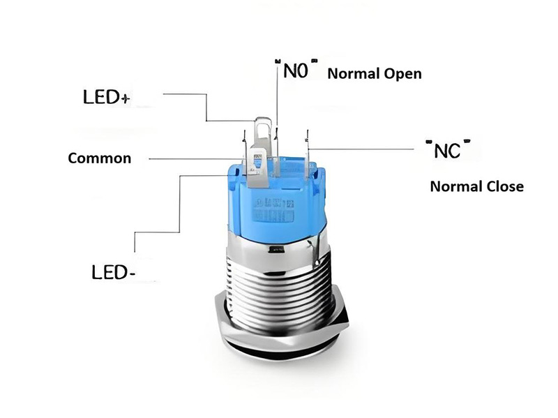
A typical illuminated body has four terminals, or four leads on a prewired version, and two of them close and open the load while the other two feed the lamp.
The contact pair is normally common plus normally open, written C and NO. A part with a normally closed contact uses C and NC instead, and an SPDT body may bring out all three. The contact side carries the load current and does not care which way it flows.
The lamp pair is an anode and a cathode, so current enters the anode and leaves the cathode, and a reversed LED simply stays dark. Nothing burns, but the panel goes out, which is why the datasheet marks one lead as positive and polarity matters only on this side.
Step 1: Read the Label and the Datasheet
Start with the marking on the body, where panel size, contact function, and voltage appear, and the LED color is usually molded into the bezel. Note those values before cutting wire, since the marking is hard to read once mounted.
Then open the datasheet, because four numbers decide the rest of the job. They are LED forward voltage, forward current, contact rating, and terminal assignment. Forward voltage varies with color, from roughly 1.8 V for red up to around 3.4 V for blue and white, and the datasheet is the only place the real value appears. A 22mm anti-vandal switch with ring illumination may use a different LED than a dot version in the same housing.
Step 2: Decide Where the LED Gets Its Power
The lamp can run from the same supply as the load or from a separate one, and the choice changes the wiring.
A shared supply is the common case, where the switch controls a 24 V circuit, the LED runs from that rail, and the resistor sees the full 24 V. A separate supply makes sense when the load voltage is high. A switch interrupting a 250 V AC circuit cannot feed its own LED from that rail without a driver, and a small 5 V or 12 V rail solves the problem.
Step 3: Size the Series Resistor
The LED has no useful internal current limit, so raising the voltage across it makes current rise steeply, the junction heat, and the part fail. The series resistor absorbs the difference between supply and forward voltage.
Vs is the supply voltage, Vf the forward voltage from the datasheet, and If the current you want, in amps. Running an indicator at its maximum rating shortens life, so half or two thirds of the rating is plenty.
| Supply Vs | Forward Voltage Vf | Forward Current If | Calculated R | Selected Standard Value |
|---|---|---|---|---|
| 5.0 V | 2.0 V | 10 mA | 300 ohm | 330 ohm |
| 5.0 V | 2.0 V | 15 mA | 200 ohm | 220 ohm |
| 12.0 V | 2.1 V | 12 mA | 825 ohm | 910 ohm |
| 24.0 V | 3.2 V | 10 mA | 2080 ohm | 2200 ohm |
The voltage and current columns are typical values. Confirm both on the datasheet, since those two numbers drive the rest of the row. Calculated resistance rarely lands on a stocked value, so round up to the next E12 step. At 12 V the math gives 825 ohm, and 910 ohm is the safe choice above it. Then check dissipation, current squared times resistance, and pick a body rated above it.
Step 4: Choose Momentary or Latching Wiring
The contact function is a purchasing decision as much as a wiring one. A momentary anti-vandal button closes while the actuator is held and opens on release. A latching version stays where you put it until the next press.
For momentary parts, wire C and NO in series with the load and the circuit runs only during the press. Latching parts wire the same way, with the difference inside the mechanism. If the load draws more than the contact rating, add a relay and let the switch drive the coil.
Step 5: Wire the Switch
Work with the panel de-energized and the supply disconnected, then strip each conductor to the length the terminal specifies. Use ferrules on stranded wire so no strand escapes and bridges to the next terminal.
Land the load circuit first, with supply to C, load to NO, and the return path back to the supply. Torque the screws to the datasheet value, then tug each wire to confirm it holds.
Then run the lamp circuit. Positive supply to the resistor, resistor to the anode, cathode to the negative return. If the lamp shares the load supply, the cathode can land on the same return point as the load. Keep that point tight, since a loose return makes the LED flicker.
Step 6: Test Before Final Assembly
Power the lamp circuit alone first, and the LED should light steadily before any load is connected. If it stays dark, reverse the two lamp leads and try again.
Then energize the load circuit with the lamp disconnected and confirm the contacts switch. A continuity check across C and NO shows open on release and closed on press.
Only after both circuits pass should the switch go into the panel and the nut be tightened. Seal the bezel per the datasheet if the panel sits outdoors.
Common Wiring Mistakes
Wiring the LED Across the Contacts
Wiring the LED across the contacts is the most frequent error, because the lamp then lights only while the contacts are closed, which turns an indicator into a circuit-active lamp. That is legitimate if you want to confirm the load is energized, and some panels do it. The tradeoff is that the lamp offers no help finding the switch in the dark, which is usually why an illuminated part was bought.
Reversed Polarity on the Lamp Leads
Reversed polarity comes second, and that one is harmless apart from the assembly time.
Shared Ground Assumption in AC Circuits
The third mistake is a shared ground assumption in AC circuits. A neutral is not a ground, and a lamp referenced to the wrong conductor will misbehave. Keep the lamp return on the conductor that feeds the supply, and never use the enclosure as a path.
Mismatched Voltage to LED Terminals
The last one is dangerous, because a 250 V AC contact rating describes the contacts and not the lamp. Line voltage into a bare LED destroys it and can damage the housing.
Ordering Samples and Drawings
The 19mm and 22mm switches differ in more than just their mounting size. Terminal spacing and connection layouts can also vary, so it is worth checking the technical drawing for the specific model before finalizing your wiring design.
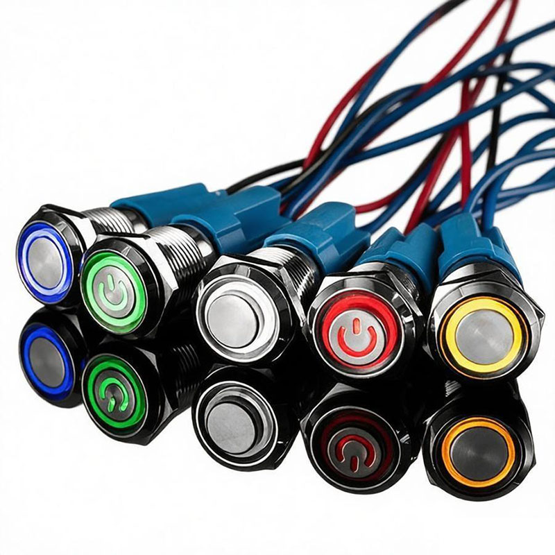
Our 19mm switch range includes different configurations, with panel cutout drawings, terminal details, and samples available to help you check compatibility before installation. IP67-rated options are also available for applications exposed to water or outdoor conditions.
If you are sourcing switches for a project, share your panel dimensions, required contact function, LED voltage, and preferred bezel finish. We can help you identify a suitable configuration.
Need wiring diagrams, custom resistor matching, or pre-wired switch harnesses? Contact our engineering team with your circuit specifications.