


Switch contacts can become discolored, overheat, or even weld together when they carry more current than they are rated for. This is particularly common in circuits powering equipment such as fuel pumps, cooling fans, and auxiliary lighting, where the current at startup can be considerably higher than during normal operation.
Repeated switching under excessive load can gradually damage contact surfaces, increase electrical resistance, and eventually cause the switch to fail. Before replacing a damaged switch, check the load’s operating and starting current against the switch’s contact ratings. The type of load and whether the circuit uses AC or DC also matter when selecting a suitable replacement.
How Excessive Current Damages Switch Contacts
Switch contacts carry current through a relatively small metal surface. Depending on the switch design, these contacts may be made from silver alloys or other conductive materials chosen for their electrical and mechanical properties.
When current passes through the contacts, a small amount of heat is generated by electrical resistance. Under normal operating conditions, the switch is designed to handle this heat. Problems can develop when the load exceeds the contact rating, particularly if the switch is used repeatedly at high current.
As the contacts heat up, their surfaces may become damaged by oxidation, arcing, or material transfer. This can increase contact resistance and produce additional heat during operation. Over time, the switch may develop intermittent connections, excessive voltage drop, or complete contact failure.
A switch that works when cold but becomes unreliable after running for a while may be showing signs of overheating. However, loose terminals, poor wiring connections, and other electrical faults can produce similar symptoms, so the contacts should not be assumed to be the only cause.
Why Switching Motors Is Harder on Contacts
Contact wear is not determined by current alone. The type of load and the conditions under which a switch opens or closes also affect its service life.
When contacts separate while current is flowing, an electrical arc may form across the opening gap. The heat generated by this arc can gradually damage the contact surfaces, especially in circuits that are switched frequently.
Motor loads are particularly demanding. Fuel pumps, cooling fans, and similar equipment can draw several times their normal running current during startup. This places additional stress on the contacts as they close.
Opening the circuit creates another challenge. Because motors are inductive loads, stored magnetic energy can produce a voltage transient when the current is interrupted. Depending on the circuit design, this may increase arcing and contact wear.
Other loads have their own characteristics. Incandescent lamps, for example, can draw high inrush current when their filaments are cold, even though they behave primarily as resistive loads during normal operation.
For this reason, a switch rated for a particular current under resistive-load conditions may not be suitable for a motor drawing the same running current. Checking the manufacturer’s load ratings is more useful than comparing amperage figures alone.
Using a Relay to Handle Higher Loads
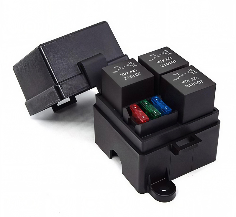
A relay allows a low-current control circuit to operate a separate circuit carrying a higher load. Instead of routing the pump or fan current through the dashboard or panel switch, the switch energizes the relay coil. The relay contacts then connect or disconnect power to the equipment.
This arrangement is common in automotive and industrial electrical systems, particularly where the control switch is too small to handle the load directly.
The relay still needs to be selected for the application. Its contact rating should account for the operating current, startup current, supply voltage, and load type. Using a relay does not eliminate contact wear, but it allows the control switch to operate within its intended electrical limits when the components are correctly matched.
The relay coil also needs consideration. As an inductive component, it can generate a voltage spike when switched off. Depending on the circuit, a flyback diode, resistor, or other suppression device may be used to protect the control switch and nearby electronics.
A diode is commonly used in DC relay circuits, although it can slow relay release. The appropriate suppression method depends on the supply type and required switching behavior.
For applications involving motors, pumps, or auxiliary lighting, a properly rated relay can provide a practical way to control higher currents without placing the full load directly on a small mechanical switch.
Relay Socket Wiring and Identification
The numbering on an ISO mini relay follows a fixed map, and knowing that map lets a technician wire a socket without guessing.
| Terminal | What It Connects to and Does |
|---|---|
| 30 | Battery positive through a fuse, the common contact that feeds the load |
| 85 | Coil negative, tied to chassis ground in most installations |
| 86 | Coil positive, fed from the control switch |
| 87 | Normally open contact, the output to the load device |
| 87a | Normally closed contact, used when the load runs with the relay at rest |
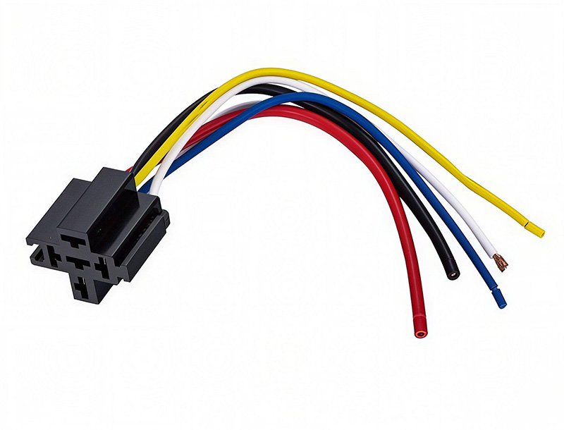
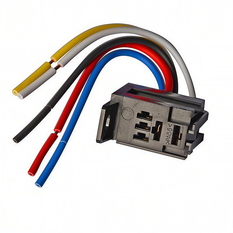
When wiring a relay socket, check the terminal numbers marked beside each connection point. These markings help identify the correct wiring positions, even after the relay has been removed. They are particularly useful during maintenance, when technicians need to trace connections or replace a relay without disturbing the existing wiring.
For a replacement, the relay’s pin arrangement, coil voltage, and contact configuration should match the original. A compatible relay can then be removed and installed without rewiring the socket. For permanent automotive installations, a car relay socket with clearly marked terminals makes wiring and future maintenance more straightforward.
Relay Socket Ratings and Performance
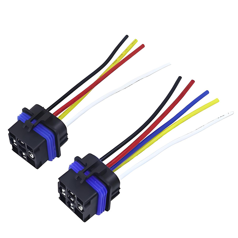
The relay socket needs to be rated for the electrical load and the conditions in which it will operate. Contact quality, terminal connections, and housing materials all affect how the assembly performs, particularly in automotive applications where heat and vibration are common.
Our JDS-3 relay socket is specified for 40 A at 27 VDC, with an operating temperature range of -40°C to +85°C. Its published specifications include insulation resistance of at least 100 MΩ, dielectric strength of 500 VAC, and contact resistance of 50 mΩ or less. The listed electrical and mechanical life figures are 100,000 and 1,000,000 operations respectively, subject to the applicable test conditions.
When selecting a relay and socket, both components need to be suitable for the intended load. A relay rated for 30 A cannot safely control a 40 A load simply because it is installed in a higher-rated socket. Likewise, using a 40 A relay with an underrated socket can lead to overheating at the terminal connections.
A removable relay also makes servicing easier, provided the socket is accessible and the replacement has the correct pin layout and electrical specifications. Our auto relay socket range includes different configurations for automotive wiring applications, allowing builders to select a model that suits the relay, mounting space, and operating environment.
Wiring and Circuit Protection
Proper wiring is just as important as choosing the right relay and socket. The load circuit should have suitable overcurrent protection, with the fuse positioned close to the power source to protect the wiring against short circuits.
The control circuit should also be protected according to its wire size and electrical requirements. Keeping the relay coil wiring separate from the high-current load path makes the installation easier to understand and helps prevent small control wires from carrying more current than they are designed for.
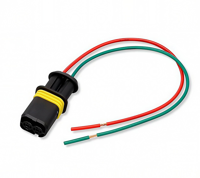
Terminal connections deserve particular attention. Use crimp terminals that match the wire gauge and socket contacts, along with the correct crimping tool. Checking each connection for secure retention before installing the harness can help prevent loose terminals and intermittent electrical faults.
Wire routing matters as well, especially in engine compartments. Keep the harness clear of excessive heat, sharp edges, and moving components, and provide adequate support where vibration could place stress on the connections.
Selecting a Switch for the Relay Coil
The switch controlling a relay normally carries only the coil current rather than the current drawn by the connected equipment. This allows a relatively low-current switch to control a higher-current load, provided its electrical rating is suitable for the coil circuit.
For a typical automotive relay, a dashboard or panel switch rated for a few amperes may be sufficient. However, the actual coil current, supply voltage, and switching characteristics should be checked before choosing a model.
If one switch operates several relays, the combined coil current needs to be considered. It is also worth checking whether the relay coils have suppression components, as these can affect switching behavior and the voltage transient generated when the circuit opens.
Our car switch range includes panel and dashboard mounting options for different automotive control applications. Along with the electrical rating, check the mounting dimensions, terminal arrangement, and switching function to ensure compatibility with the intended installation.
Samples and Customization for Automotive Projects
For new wiring harnesses or automotive electrical assemblies, testing a sample can help confirm whether the socket fits the relay and mounting arrangement. It also gives engineers an opportunity to check terminal retention, wiring clearance, and installation space before moving into production.
We can provide samples of the JDS-3 and other relay socket models for evaluation. OEM and ODM services are also available for projects requiring specific wire lengths, housing colors, or packaging arrangements.
If you are sourcing relay sockets for an automotive project, share the relay model, expected load current, and any mounting or wiring requirements. Our team can review the specifications, provide available drawings, and help identify suitable samples for testing.